
Typical Solution: VRU/VRP — Incoming Distribution Devices for Buildings
Typical solution for 0.4 kV main incoming distribution boards (VRU/VRP): working drawings for 400 A and 1600 A cabinets — single-line diagrams, secondary circuits, bills of materials. PDF open access, DWG on request.
Published: 11.06.2026 · Author: engineering department of LK Energy LLC
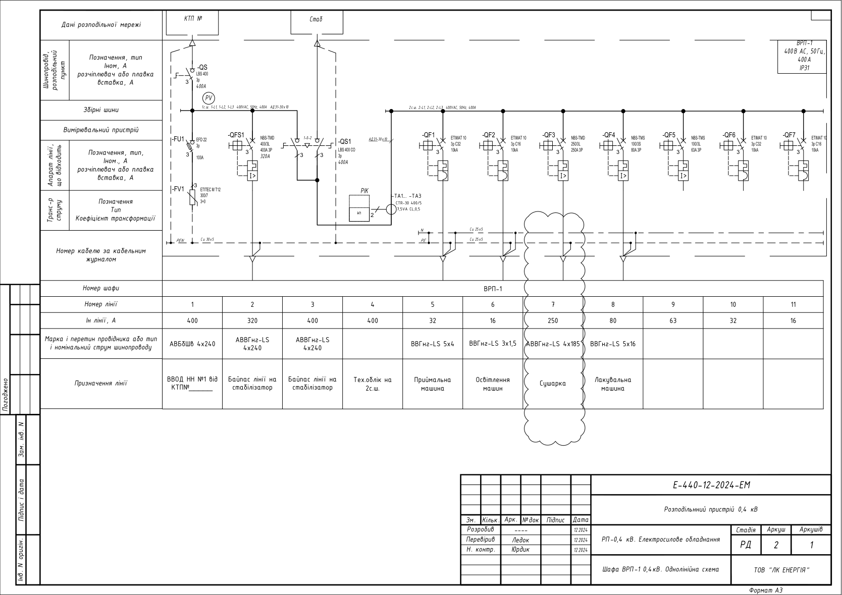
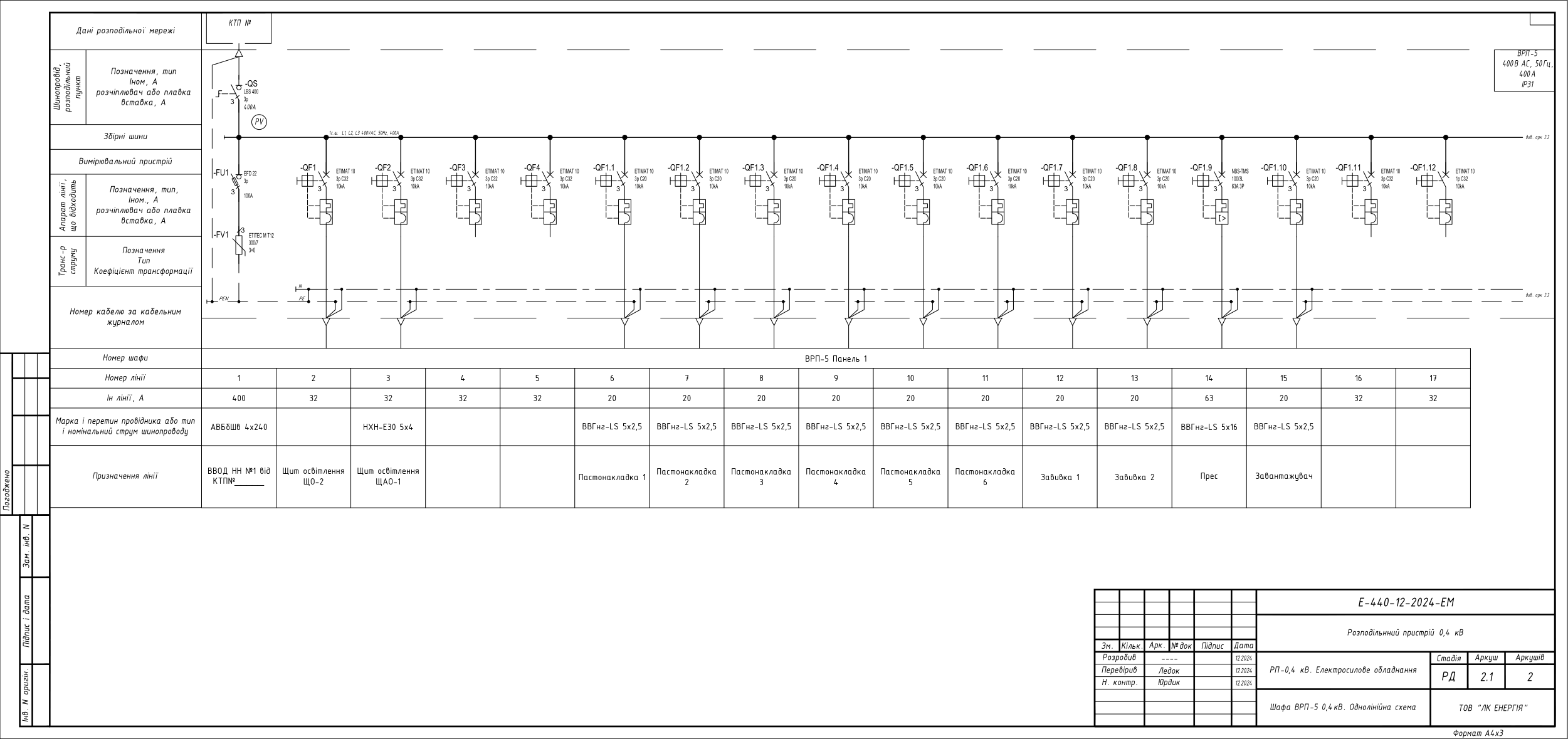
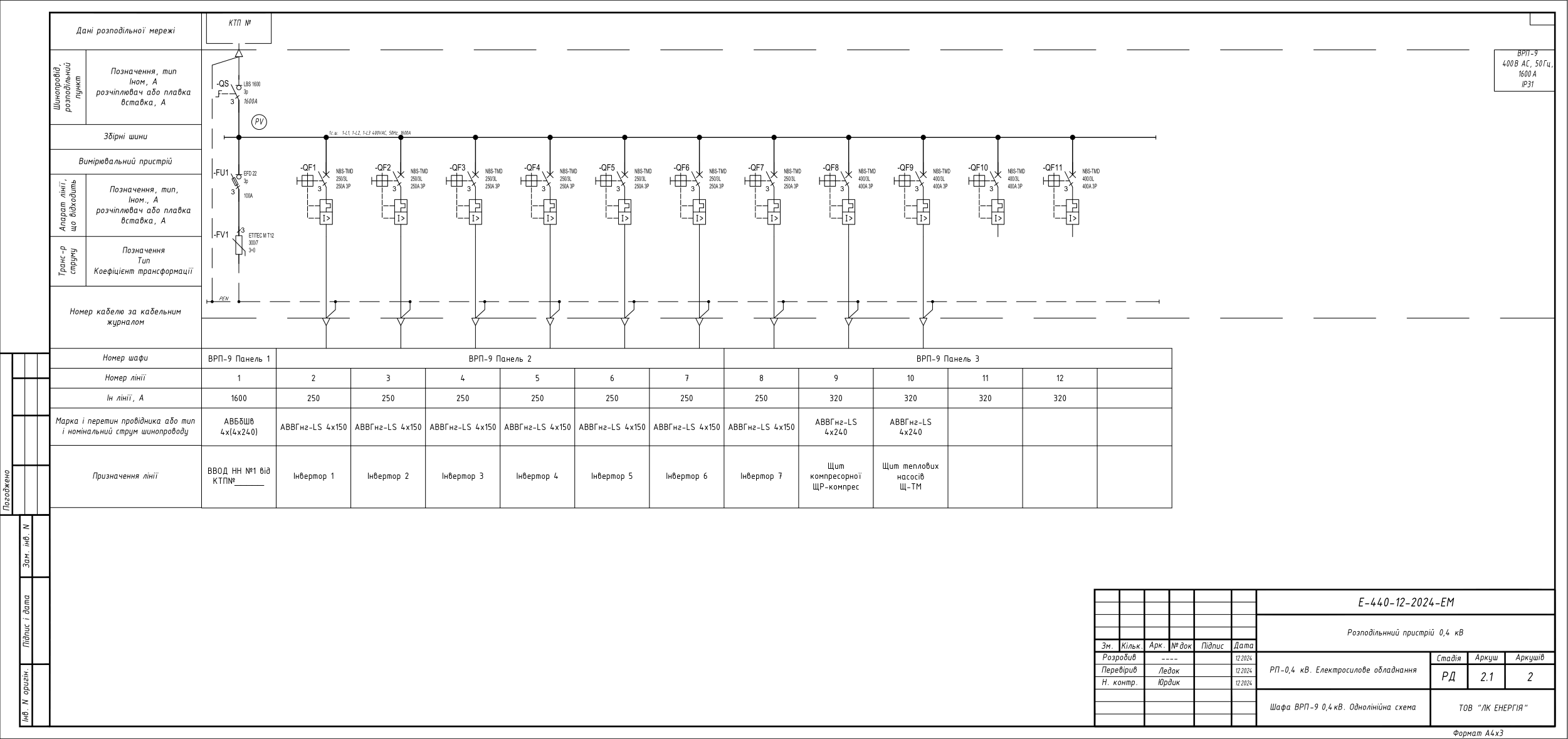
Working drawings of the typical solution for 0.4 kV main incoming distribution boards (VRU/VRP) for buildings and industrial facilities: three cabinets from a real 2024 order — a 400 A VRP with a metering unit and a "1-0-2" switch (direct supply or via a voltage stabilizer — bypass), a 400 A distribution VRP for 17 lines, and a 1600 A VRP on three panels. Each set includes a single-line diagram, a secondary-circuit connection diagram, a general view of the cabinet and a bill of materials (20 sheets in total). The PDF is freely available below; the DWG package is provided free of charge on request via the form.
What is a VRU, and how does it differ from a GRShch (main switchboard)
VRU is a main incoming distribution device: a set of switching and protective apparatus and metering instruments installed at the incoming point of a 0.4 kV supply line into a building. The VRU receives power from a transformer substation (KTP) or the supply network, allows the entire electrical installation to be disconnected, provides metering, protection against overloads and short circuits, and distributes power among distribution and group panels. VRP is a main incoming distribution device; VRP more often denotes a specific cabinet or panel from which a VRU is assembled.
GRShch is the main distribution switchboard. The functions are the same — receive electricity, perform metering and distribute it — but the term GRShch is usually used for the incoming board of large buildings and industrial facilities: multiple incomers, busbar sectionalizing, automatic transfer switch (ATS/AVR), and supply to critical consumers. In practice the terms are often used as synonyms; the exact composition is determined by the project: for residential buildings and smaller facilities, VRU/VRP is more commonly used, while GRShch is used for facilities with a more developed power supply scheme.
This typical solution presents a lineup of VRP cabinets for a single facility in three typical configurations: an incoming cabinet with metering and backup, a distribution cabinet for process equipment, and a high-capacity 1600 A incoming cabinet that collects inverter feeders and power panels.
Technical parameters of the solution
Common to the set:
- Network: 400 V AC, 50 Hz; IP31 enclosure — ShK frame cabinets (2200×900×600, 2000×600×600) with a 100 mm plinth, manufactured by LK Energy; cable entries from above
- Surge protection: ETITEC M T12 300/7 (3+0) surge arrester behind an EFD 22 100 A disconnector with CH22x58 gG fuses
- Voltage monitoring: 0–400 V voltmeter with a CS 16 66 U phase selector switch, phase-presence indicator lamps on the doors
- ETI switching and protective apparatus (LBS, NBS-TM, ETIMAT 10); metering via a NIK 2301 AP3 transformer-connected meter
- Design stage: detailed design (RD); year of development: 2024; drawing language: Ukrainian
Design 1 — 400 A VRP with metering and backup input: LBS 400 incomer + NBS-TMD 400/3L (36 kA) circuit breaker; LBS CO 400 "1-0-2" switch: direct supply or via a stabilizer (bypass); two AD31 30×10 busbar sections; outgoing lines NBS-TMD 250/3L, NBS-TMS 100 (63 and 80 A), ETIMAT 10 3p C16/C32 modular breakers; technical metering on section 2 — NIK 2301 + CTR-30 400/5 accuracy class 0.5 current transformers + test terminal block. In this solution the backup is switched on manually via the switch; for automatic transfer of the backup supply, see the typical solution for 0.4 kV automatic transfer switches (ATS/AVR).
Design 2 — 400 A distribution VRP: LBS 400 incomer; a single 400 A busbar section; two mounting panels in a 2200×900×600 ShK cabinet; 17 outgoing lines — ETIMAT 10 3p C20/C32 (10 kA) and NBS-TMS 100/3L 63 A (process equipment and lighting panels); metering via NIK 2301 + CTR-30 150/5.
Design 3 — 1600 A VRP on three panels: LBS 1600 incomer; 1600 A busbars (input via AVBbShv 4×(4×240) cables); 7 NBS-TMD 250/3L 250 A feeders (inverter lines) + 4 NBS-TMD 400/3L feeders set at 320 A (compressor room panel, heat pump panel, backup).
The ratings of a specific design (incomer current, number and settings of outgoing lines, metering unit) are agreed based on the technical questionnaire.
Package contents and downloads
| No. | Document | Contents | File |
|---|---|---|---|
| 1 | 400 A VRP cabinet with metering and backup input | Single-line diagram, secondary circuits, general view, bill of materials (6 sheets) | |
| 2 | 400 A distribution VRP cabinet for 17 lines | Single-line diagram for 2 panels, secondary circuits, general view, bill of materials (7 sheets) | |
| 3 | 1600 A VRP cabinet on three panels | Single-line diagram, secondary circuits, general views of the panels, bill of materials (7 sheets) |
Preview
DWG package on request
The full DWG assembly of the order — 10 cabinets in a single AutoCAD file (VRP-1…VRP-6, VRP-9 and the facility's distribution panels): single-line diagrams, secondary circuits, general views, bills of materials. We will send it to your email free of charge.
Frequently asked questions
Can these diagrams be used in the design of my own building?
Yes — as a typical base solution for the electrical (EM/EP) section. Site adaptation, load calculation and compliance with the current PUE (electrical installation rules) / DSTU (Ukrainian national standards) is the responsibility of the design engineer. The drawings were produced for a real 2024 production order by LK Energy (detailed design stage).
How does a VRU differ from a GRShch?
The functions are the same — receive 0.4 kV electricity, perform metering and distribute it. VRU/VRP is the typical name for a building's incoming device; GRShch usually refers to the incoming board of large facilities with multiple incomers, busbar sectionalizing and an automatic transfer switch (ATS/AVR). In practice the terms are often used as synonyms; the exact composition is determined by the project.
What equipment is used in the diagrams?
LBS 400/1600 load-break switches, NBS-TM circuit breakers and ETIMAT 10 modular breakers, ETITEC M T12 surge arresters, EFD disconnectors with fuses manufactured by ETI; metering via NIK 2301 with CTR-30 current transformers. A design using other equipment is agreed based on the technical questionnaire.
How do I get the DWG files?
Fill out the form on this page — we will send the DWG assembly of all the order's cabinets to your email within one business day, free of charge.
Does LK Energy manufacture VRU/VRP cabinets?
Yes. We manufacture VRP cabinets, ShK frame enclosures, and 0.4 kV switchgear equipment at our own production facility in Odesa. We advise design engineers on configuration and on filling out technical questionnaires: +38 067 104 94 91. See also: typical solution for a 10/0.4 kV transformer substation (KTP) with a low-voltage switchgear (RUNN), ShchO-90 panel for a package transformer substation (ZTP), 0.4 kV automatic transfer switch (ATS/AVR).
The diagrams are provided as a reference typical solution. Site adaptation, verification of protective-device selectivity and compliance with applicable standards (PUE, DSTU, DBN — Ukrainian building codes) is the responsibility of the design engineer. LK Energy is not liable for the application of this solution without adaptation to the conditions of a specific facility.
Any questions left?
Write or call us — we answer to the point. Preliminary reply within 24 hours.
+380 67 104 94 91