
Standard Solution: 6(10) kV Switchgear (RP) on KRU-E Switchgear Panels (KM-1F Envelope) with MRZS Terminals
Standard solution: 6 kV switchgear (RP) on KM-1F panels with MRZS terminals — 158 sheets of protection and automation (RZA) schematics, ATS, central signaling, and an operating manual. PDF freely available, DWG on request.
Published: 11.06.2026 · Author: Engineering Department, LK Energy LLC
A ready-made set of Stage P protection and automation (RZA) schematics for a 6(10) kV switchgear (RP) built on KRU-E withdrawable-element switchgear panels in the KM-1F envelope with MRZS microprocessor-based protection terminals: 158 sheets in the consolidated set — two incomers, a bus-tie circuit breaker with automatic transfer switching (ATS), a bus-tie disconnector with central signaling (CS), two voltage transformers, two auxiliary-supply transformers (TVP) with an auxiliary-supply ATS (ATS-SN) circuit, outgoing feeders (including one with a commercial metering unit), and inter-panel connections. The set also includes a technical questionnaire and an 85-page KM-1F operating manual. The schematics were developed by LK Energy engineers based on an actual reconstruction project for an operating facility (2025). The PDF is freely available below; the DWG is available on request via the form.
What sets the KM-1F design with MRZS apart
This solution is the fourth hardware platform in our RP lineup. For an explanation of what a 6(10) kV switchgear (RP) is and when a double-bus-section design is used, see the page on the baseline solution on KSO cubicles. Here we address the same task on a fundamentally different equipment base:
- Withdrawable elements instead of fixed cubicles
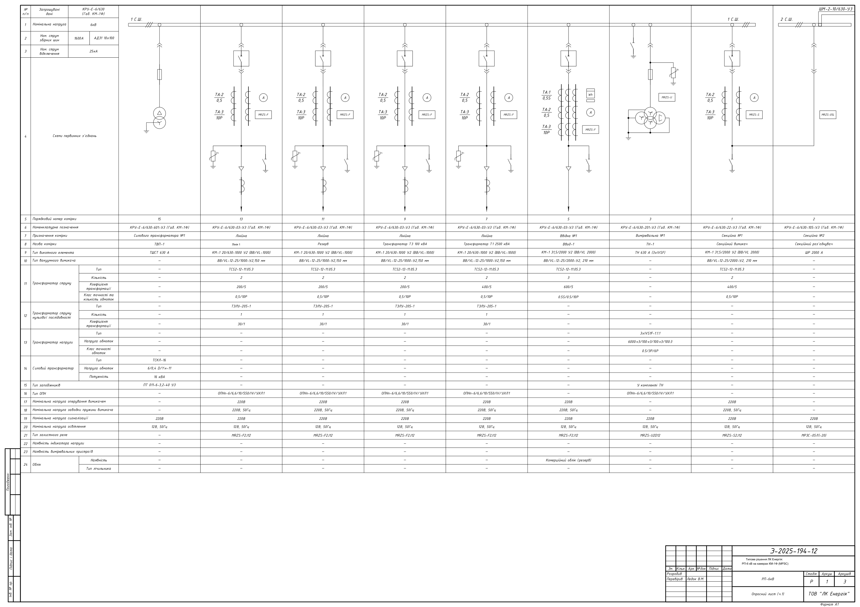
- KRU-E-6/630 cabinets (KM-1F envelope) with KM-1 withdrawable elements: BB/VL-12-25/2000-U2 vacuum circuit breakers on the incomers and bus-tie breaker, BB/VL-12-25/1000-U2 on the feeders, a withdrawable 630 A voltage transformer, a 630 A TShST busbar element in the TVP cubicles, and a 2000 A ShR busbar element in the bus-tie disconnector cubicle. Front-access maintenance, IP41 protection rating with the doors closed.
- MRZS terminals instead of RS83
- MRZS-F2J12 — incomers and outgoing feeders, MRZS-S2J12 — bus-tie circuit breaker, MRZS-U2D12 — voltage transformer cubicles, MRZS-05L — central signaling.
- CS — central signaling
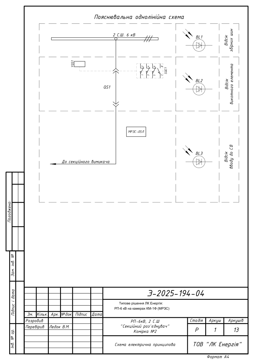
- The bus-tie disconnector cubicle implements the RP central signaling circuit on an MRZS-05L(CS) terminal: alarm signaling buses, "dark bus" monitoring, and a "CS fault" signal.
- ATS at two levels
- ATS on the bus-tie circuit breaker with voltage interlocks from both sections' voltage transformers, plus auxiliary-supply ATS (ATS-SN) on the TVP side.
- Commercial metering unit
- A dedicated outgoing-feeder design with metering circuits (class 0.5S current transformers, a meter mounting position) and a commercial metering reserve on the incomers.
- 1600 A busbars
- (AD31 10×100), 16 cubicles across two bus sections, 25 kA thermal withstand rating.
Technical parameters of the solution
- Rated voltage: 6 kV (6(10) kV class, highest operating voltage 7.2 kV); two bus sections, 16 cubicles
- Busbars: 1600 A (AD31 10×100); main circuits 630 A
- Thermal withstand 25 kA (3 s), dynamic withstand 51 kA
- Cabinets: KRU-E-6/630-03/-22/-105/-201/-601-U3 in the KM-1F envelope, with withdrawable elements, front-access maintenance, IP41
- Switching: BB/VL-12-25/2000-U2 (210 mm) and BB/VL-12-25/1000-U2 (150 mm) vacuum circuit breakers on KM-1 withdrawable elements
- Protection: MRZS microprocessor-based terminals — MRZS-F2J12, MRZS-S2J12, MRZS-U2D12, MRZS-05L (CS)
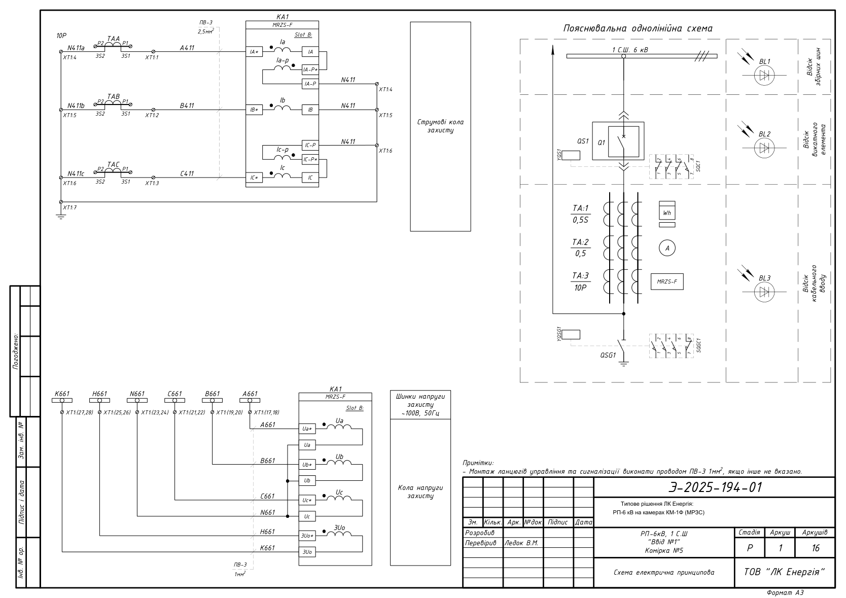
- Measurement: TCS2-12-11.05.3 current transformers (200/5, 400/5, 600/5; class 0.5/10P, 0.5S/0.5/10P on the incomers), TZLU-205-1 30/1 zero-sequence current transformers on the feeders
- Voltage transformer: 3×IVS1F-1.1.1, 6000:√3/100:√3/100:√3/100:3, class 0.5/3P/6P, 630 A withdrawable element
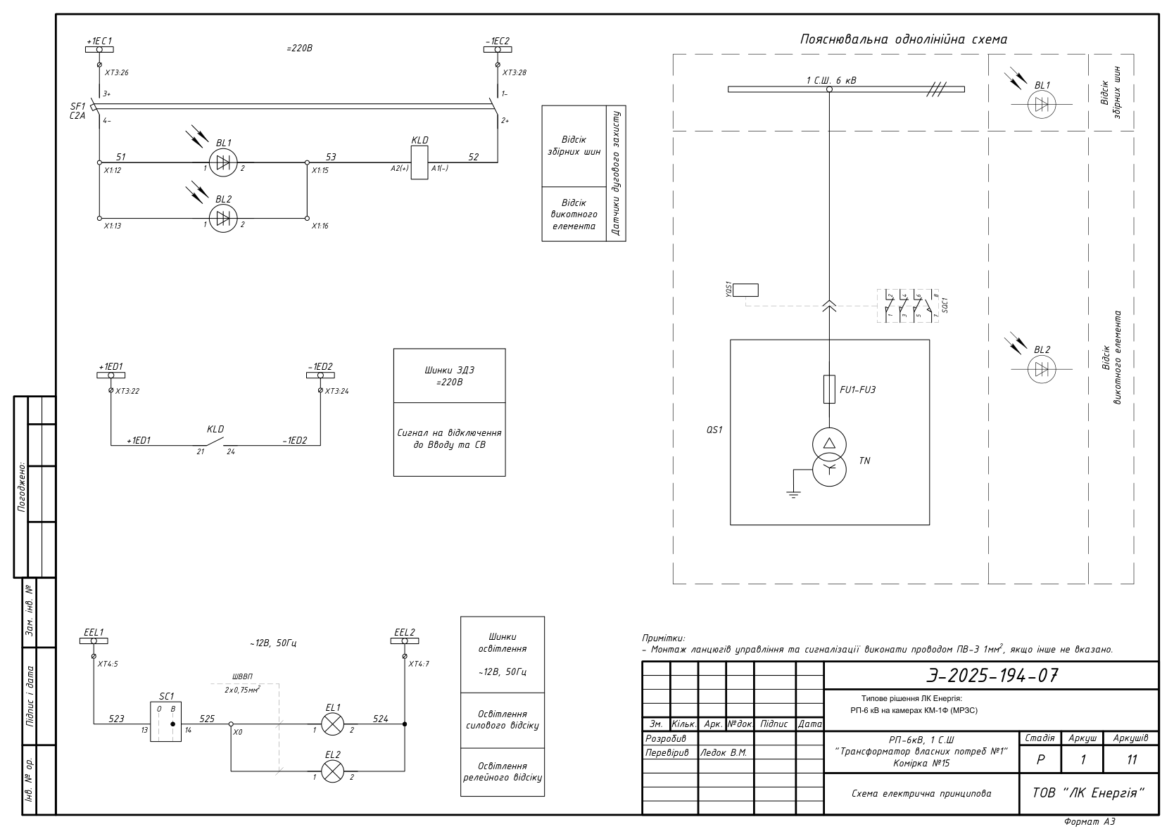
- Auxiliary supply: TSKL-16 auxiliary transformer (TVP) (16 kVA, 6/0.4 kV D/Yn-11) with PT 011-6-3.2-40 U3 fuses + ATS-SN
- Surge protection: OPNp-6/6.6/10/550/IV/UKhL1 surge arresters
- Auxiliary circuits: control and signaling 220 V; voltage-transformer circuits 100 V; compartment lighting 12 V
- Climatic design category U3; technical specification TU U 27.1-40132794-001:2016
- Year developed: 2025, Stage P, schematic language Ukrainian, format DWG (AutoCAD)
- Ratings for a specific implementation are agreed via the technical questionnaire
Package contents and downloads
| No. | Function | Cubicle | Equipment | Sheets | File |
|---|---|---|---|---|---|
| 1 | Incomer No. 1, Bus Section 1 | Cubicle No. 5 | BB/VL-12-25/2000-U2, MRZS-F2J12, TCS2-12 600/5 (0.5S/0.5/10P) | 16 | |
| 2 | Incomer No. 2, Bus Section 2 | Cubicle No. 6 | BB/VL-12-25/2000-U2, MRZS-F2J12, TCS2-12 600/5 (0.5S/0.5/10P) | 16 | |
| 3 | Bus-tie circuit breaker (ATS) | Cubicle No. 1 | BB/VL-12-25/2000-U2, MRZS-S2J12, TCS2-12 400/5 | 16 | |
| 4 | Bus-tie disconnector + CS | Cubicle No. 2 | ShR 2000 A, MRZS-05L — central signaling | 13 | |
| 5 | Voltage transformer VT-1 | Cubicle No. 3 | 3×IVS1F-1.1.1 (0.5/3P/6P), MRZS-U2D12, 630 A withdrawable voltage transformer | 15 | |
| 6 | Voltage transformer VT-2 | Cubicle No. 4 | 3×IVS1F-1.1.1 (0.5/3P/6P), MRZS-U2D12, 630 A withdrawable voltage transformer | 15 | |
| 7 | Auxiliary-supply transformer No. 1 (TVP) + ATS-SN | Cubicle No. 15 | TSKL-16 (16 kVA, 6/0.4 kV), TShST 630 A, ATS-SN circuit | 11 | |
| 8 | Auxiliary-supply transformer No. 2 (TVP) | Cubicle No. 16 | TSKL-16 (16 kVA, 6/0.4 kV), TShST 630 A | 9 | |
| 9 | Outgoing cable feeder, Bus Section 1 | Cubicles No. 7–13 | BB/VL-12-25/1000-U2, MRZS-F2J12, TZLU-205-1 | 12 | |
| 10 | Outgoing cable feeder, Bus Section 2 | Cubicles No. 8–14 | BB/VL-12-25/1000-U2, MRZS-F2J12, TZLU-205-1 | 12 | |
| 11 | Outgoing feeder with commercial metering | Cubicle No. 10 | BB/VL-12-25/1000-U2, MRZS-F2J12, 0.5S current transformers, metering circuits | 14 | |
| 12 | Inter-panel connections | — | Cable connection tables for control and signaling circuits | 6 | |
| 13 | Technical questionnaire (KRU-E-6/630, KM-1F envelope) | — | Single-line diagrams for 16 cubicles + layout plan | 3 | |
| 14 | KM-1F operating manual | — | Description, BB/VL circuit breaker, withdrawable elements, terminals, maintenance, warranty — 85 pp. | 85 |
The cubicle sections with circuit breakers contain schematic diagrams of the current protection circuits, voltage circuits, control and signaling circuits, compartment lighting circuits, and an explanatory single-line diagram. The operating manual is a separate manufacturer document: it describes the KM-1F design, the operation of the vacuum circuit breaker and the withdrawable element, the protection terminals, maintenance, and warranty terms.
Schematic previews
DWG package on request
We will send you the full DWG package (a consolidated file of schematics for all 16 cubicles: incomers, bus-tie circuit breaker, bus-tie disconnector with CS, voltage transformers, TVP with ATS-SN, outgoing feeders, inter-panel connections, plus the technical questionnaire) to your email free of charge.
Frequently asked questions
How does this solution differ from an RP on KSO cubicles?
The RP configuration is the same — two bus sections, incomers, a bus-tie device, feeders, voltage transformers, and auxiliary-supply transformers — but the equipment base is different: KRU-E cabinets in the KM-1F envelope with withdrawable elements (the BB/VL circuit breakers roll out together with the truck) instead of fixed KSO cubicles, MRZS terminals instead of RS83, 1600 A busbars, and central signaling on MRZS-05L. Compare with: the baseline 10 kV RP solution on KSO (VV-N10, RS83-AV2) and the KSO variant with VV/TEL circuit breakers.
Can these schematics be used in a working design project?
Yes — as a standard baseline solution. Site-specific adaptation, RZA setpoint calculation, the cable schedule, and compliance with the applicable PUE (electrical installation rules) and DSTU (Ukrainian national standards) are the responsibility of the design engineer. The schematics correspond to an actual reconstruction project for an operating facility, developed in 2025 (Stage P).
What does the operating manual cover?
85 pages: a description of the KM-1F design and technical specifications, the layout of the compartments, the operation of the vacuum circuit breaker and the withdrawable element, operational interlocks, protection terminals, inspection and repair intervals, transportation, storage, and the manufacturer's warranty terms. For a design engineer, this is a ready-made source of RP operating requirements that otherwise usually has to be pieced together from various sources.
How do I get the DWG files?
Fill in the form on this page — we will send the DWG package to your email within one business day.
Does LK Energy manufacture KM-1F panels to these schematics?
Yes. KRU-E cabinets in the KM-1F envelope are manufactured to specification TU U 27.1-40132794-001:2016 at our own production facility in Odesa — to customer schematics agreed with the manufacturer. See also our equipment catalog. We will help adapt the solution and fill in the technical questionnaire: +38 067 104 94 91.
The schematics are provided as a reference standard solution. Site-specific adaptation, RZA setpoint calculation, and compliance with applicable codes (PUE, DSTU, DBN — Ukrainian building codes) are the responsibility of the design engineer. LK Energy is not liable for use of the solution without adaptation to the conditions of a specific facility.
Any questions left?
Write or call us — we answer to the point. Preliminary reply within 24 hours.
+380 67 104 94 91