
Typical Solution: KRUN — Outdoor-Installation Switchgear Cells 10 kV
Ready-made relay protection and automation schematics for outdoor-installation KRUN 10 kV switchgear: 148 sheets, 2 configurations — incomers, bus-section breaker with ATS, feeders, VT, and station-service transformer cells. PDF open access, DWG on request.
Published: 11.06.2026 · Author: Engineering Department, LK Energy LLC
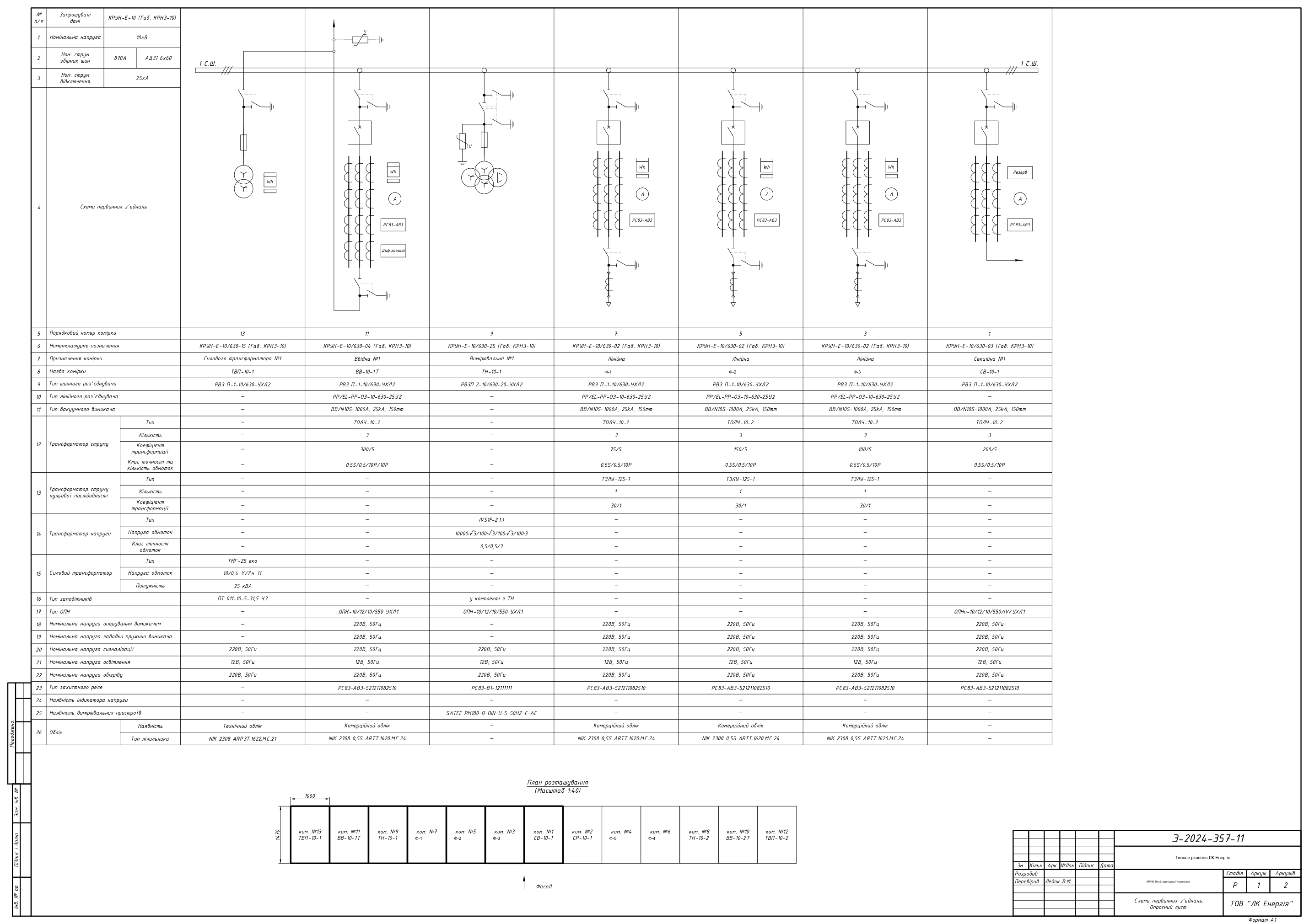
A ready-made set of Stage R (design documentation stage) relay protection and automation (RPA) schematic diagrams for KRUN — outdoor-installation switchgear cells 10 kV of the KRUN-E-10 series (KRN3-10 envelope) in two configurations: a two-section switchgear with 13 cells (105 sheets) and a single-section switchgear with 7 cells (43 sheets). The schematics were developed by LK Energy engineers for an actual 2024 order for two operating substations. The PDF is freely available below; the DWG package (18 files) is available on request via the form.
What KRUN Is and When It Is Used
KRUN 10 kV is a factory-assembled switchgear built from metal-enclosed outdoor-installation cells in their own enclosure with heating and lighting: it operates in the open air, without a separate indoor switchgear building. It is used when a 10 kV switchgear needs to be sited on an open pad — at 35/10 kV substations, when reconstructing existing substations without erecting a new building, or for connecting new consumers or lines.
Each KRUN cell is a functionally complete unit: an incomer, a bus-section breaker, a feeder, a voltage transformer (VT), or a station-service transformer (SST). In this solution, the breaker cells are built on microprocessor-based protection terminals that, in addition to the basic protection stages, implement breaker failure protection (BFP), bus logic protection (BLP), and automatic frequency load shedding (AFLS) — in the configuration confirmed by the schematics: BFP/BLP/AFLS on the incomers and feeders, and, on the incomers and bus-section breaker, also automatic transfer switching (ATS), with station-service ATS on the SST of one configuration.
This typical solution covers a standard designer task: a single-line diagram of the primary connections of the KRUN 10 kV switchgear plus complete schematic RPA diagrams for every cell — for both the two-section and the single-section layout.
Technical Parameters of the Solution
- Series: KRUN-E-10 (KRN3-10 envelope), rated voltage 10 kV
- Busbars: 870 A (AD31 6x60), rated breaking current 25 kA
- Configuration A: 2 busbar sections, 13 cells (2 incomers, bus-section breaker, bus-section disconnector, 5 feeders, 2 VTs, 2 SSTs)
- Configuration B: 1 busbar section, 7 cells (incomer, 4 feeders, VT, SST)
- Switching: vacuum circuit breakers VV/N10S-1000A, 25 kA
- Protection: microprocessor-based terminals RS83-AV3 (incomers, feeders, bus-section breaker), RS83-V1 (metering cell)
- Functions per schematics: BFP, BLP, AFLS, ATS (incomers/bus-section breaker), station-service ATS
- Metering: CT TOLU-10-2 (0.5S/0.5/10P), zero-sequence CT TZLU-125-1 (30/1), VT 3xZNOLP-2IO (per schematics; in the donor questionnaire — IVS1F-2.1.1)
- Disconnectors: busbar RVZ P-1-10/630-UHL2, line RR/EL-RR-OZ-10-630-25U2
- Surge arresters: OPN-10/12/10/550
- Metering: commercial and technical — NIK 2308 meters (0.5S), SATEC PM180 measuring device
- SST: TMG-25 eco, 10/0.4 kV, 25 kVA
- Auxiliary circuits: 220 V, 50 Hz; lighting 12 V; heating 220 V
- Year of design: 2024, schematic language — Ukrainian, format DWG (AutoCAD), Stage R
- Other parameters of a specific implementation (rated connection currents, CT ratios, protection composition) — per the questionnaire
Package Contents and Downloads
Configuration A — Two-Section KRUN 10 kV, 13 Cells (105 Sheets)
| No. | Section | Purpose | Equipment | Sheets | Schematics |
|---|---|---|---|---|---|
| 1 | Primary connections diagram + questionnaire | Single-line diagram of the entire switchgear, cell layout plan | KRUN-E-10/630 | 2 | |
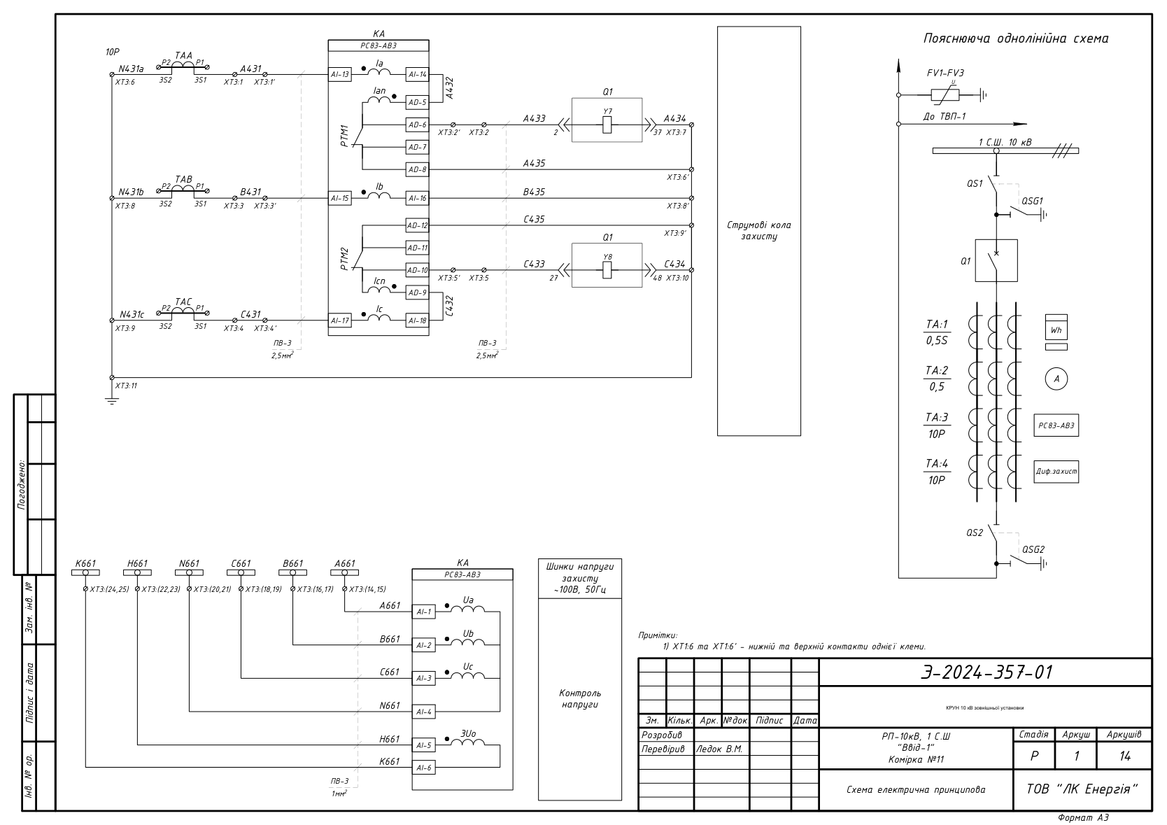
| 2 | Incomer-1 (cell no. 11) | Supply incomer, busbar section 1 | VV/N10S, RS83-AV3, TOLU-10-2 | 14 | |
| 3 | Incomer-2 (cell no. 10) | Supply incomer, busbar section 2 | VV/N10S, RS83-AV3, TOLU-10-2 | 14 | |
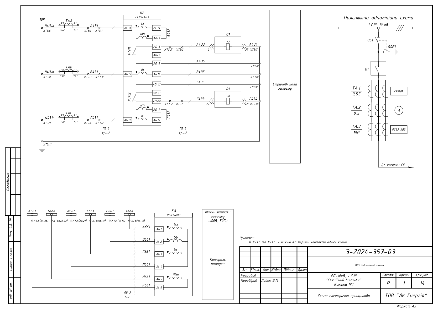
| 4 | Bus-section breaker (cell no. 1) | Sectionalizing between busbar sections 1 and 2, ATS | VV/N10S, RS83-AV3 | 14 | |
| 5 | Bus-section disconnector (cell no. 2) | Bus-section disconnector, signaling circuits | RVZ P-1-10/630 | 7 | |
| 6 | VT-1 (cell no. 9) | Voltage metering, busbar section 1 | 3xZNOLP-2IO, RS83-V1 | 9 | |
| 7 | VT-2 (cell no. 8) | Voltage metering, busbar section 2 | 3xZNOLP-2IO, RS83-V1 | 9 | |
| 8 | SST-1 (cell no. 13) | Station-service transformer, station-service ATS | TMG-25 | 7 | |
| 9 | SST-2 (cell no. 12) | Station-service transformer | TMG-25 | 5 | |
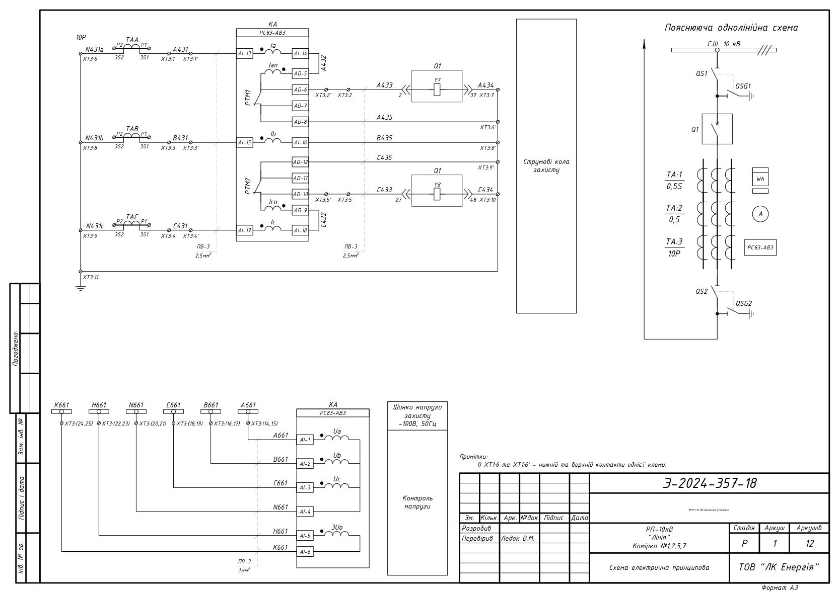
| 10 | Feeder cells, busbar section 1 (cable) | Outgoing 10 kV feeders | VV/N10S, RS83-AV3, TZLU-125-1 | 12 | |
| 11 | Feeder cells, busbar section 2 (cable) | Outgoing 10 kV feeders | VV/N10S, RS83-AV3, TZLU-125-1 | 12 |
Configuration B — Single-Section KRUN 10 kV, 7 Cells (43 Sheets)
| No. | Section | Purpose | Equipment | Sheets | Schematics |
|---|---|---|---|---|---|
| 1 | Primary connections diagram + questionnaire | Single-line diagram, layout plan | KRUN-E-10/630 | 1 | |
| 2 | Incomer (cell no. 3) | Supply incomer | VV/N10S, RS83-AV3 | 14 | |
| 3 | VT (cell no. 6) | Voltage metering | 3xZNOLP-2IO, RS83-V1 | 9 | |
| 4 | SST (cell no. 4) | Station-service transformer | TMG-25 | 7 | |
| 5 | Feeder cells (overhead connections) | Outgoing 10 kV feeders | VV/N10S, RS83-AV3 | 12 |
VT type: 3xZNOLP-2IO in the schematics; IVS1F-2.1.1 in the donor questionnaire (to be agreed at the time of ordering).
The breaker-cell sections include current protection circuits, control and signaling circuits, metering circuits, compartment lighting and heating circuits, and an explanatory single-line diagram.
Schematic Previews
DWG on Request
We will send the full package of 18 DWG files (schematics for all cells of both configurations, primary connections diagrams, inter-cell links) to your email free of charge.
Frequently Asked Questions
Can these schematics be used in a working design project?
Yes — as a typical baseline solution. Site-specific adaptation, RPA setpoint calculation, cable schedule, and compliance with the applicable PUE (Electrical Installation Rules) and DSTU (Ukrainian national standards) are the responsibility of the design engineer. The schematics correspond to an actual order for KRUN-E-10 cells for two operating substations (2024).
What equipment is specified in the schematics?
Vacuum circuit breakers VV/N10S-1000A (25 kA), microprocessor-based terminals RS83-AV3 and RS83-V1, current transformers TOLU-10-2 and TZLU-125-1, voltage transformers 3xZNOLP-2IO (IVS1F-2.1.1 in the donor questionnaire), SST TMG-25, NIK 2308 meters, SATEC PM180 measuring device. Our archive also holds versions built on other equipment — get in touch.
What is the difference between Configurations A and B?
Configuration A is a two-section switchgear with 13 cells: two incomers, a bus-section breaker with ATS, a bus-section disconnector, five feeders, two VTs, and two SSTs. Configuration B is a single-section switchgear with 7 cells: one incomer, four feeders with overhead connections, a VT, and an SST. Both are built from identical KRUN-E-10 cells with identical equipment.
Does LK Energy manufacture KRUN cells to these schematics?
Yes. KRUN-E-10 is LK Energy's own serial production in Odesa; we also manufacture KSO/KRU cells, low-voltage switchgear cabinets, and ShchO-90 panels.
Will you help adapt the solution to my facility?
Yes, we advise design engineers on equipment selection, non-standard designs, and filling in the questionnaire: +38 067 104 94 91.
The schematics are provided as a reference typical solution. Site-specific adaptation, RPA setpoint calculation, and compliance with applicable standards (PUE, DSTU, DBN — State Building Codes) are the responsibility of the design engineer. LK Energy is not liable for use of the solution without adaptation to the conditions of a specific facility.
Any questions left?
Write or call us — we answer to the point. Preliminary reply within 24 hours.
+380 67 104 94 91